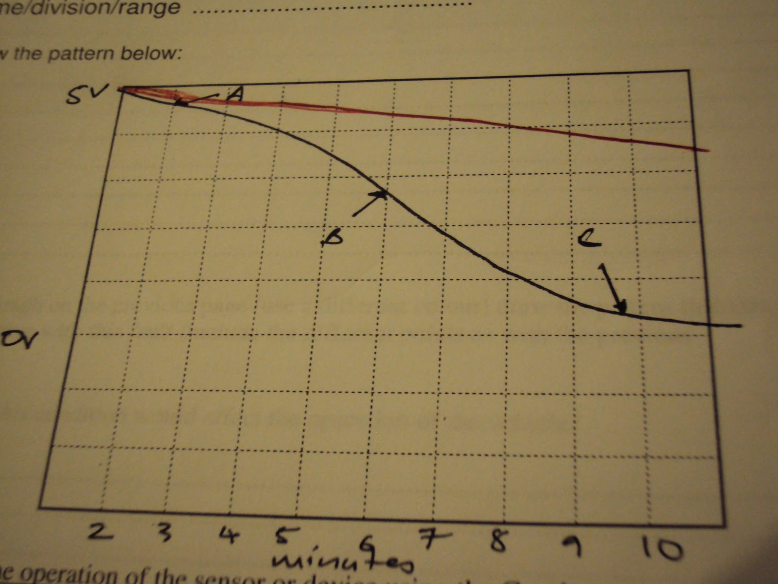
Throttle Position Sensor

A - Throttle opening and more air is coming in as the throttle is opening.
B - The throttle is stable for a small time and then starts decelerating. Throttle closing slowly.
C - Throttle is closed
D - Engine is accelerating heavily and fully opening.
E - engine at wide open throttle and stays wide open for a while
F - decelerating again and going back to closed throttle.
Drawing A - in red shows that the signal is not grounding back to the ecu.There is an open circuit in the earth wire that goes back to the ecu. Therefore the signal is always reading supply voltage as the voltage is not dropping in the variable resistor.This can be also caused if the signal has shorted to supply voltage. By this voltage the ecu will always think the throttle is fully open. The engine probably wont start as it will flood the engine thinking its at wide open throttle
Drawing B - Theres no reference voltage to thew TPS. Theres no signal voltage out when theres no reference voltage.
Drawing C - If there is a high resistance at ground. The signal is always high even at closed throttle. As there is high resistance at the ground, there is a less voltage drop at the variable resistor therefore the signal picks up a higher voltage even at closed throttle. The engine will be very rough and run rich as it will think that its at full throttle when its only opening a little bit. The fuel economy will go high and run really badly.
Map Sensor

A - The engine decelerating and the throttle is closing causing more vacuum in the engine so the voltage goes down.
B - At closed throttle the vacuum is high so the voltage stays low.
C - Thew engine accelerated so there was more air pressure and vacuum goes down so voltage increases.
D - engine decelerating and throttle closing co less air is coming in and vacuum is increasing so the voltages decreases.
A high resistance at ground will mess up signals. The signal outputs will go down as there is mores resistance added in the circuit with the wheat stone bridge.More resistance added to the circuit will make the output low. So the voltage output is lower as shown in the graph in red. With this problem the engine will operate really badly. There will be more air coming into the engine but the map will tell the ecu that there less air coming. The engine will be running very lean. Will be hard to start and engine will keep dying at idle. It will have no power.
Engine Coolant Temperature Sensor
A - Engine is cold so the voltage output is high.
B - as the engine is warming up the voltage is dropping
C - engine is warmed up or hot so the voltage is really low.
If there is a open circuit in ground, signal will always read 5v as thats is the supply form the ecu and there is no voltage at the thermistor and the internal resistor in the ecu.
the fault in my graph has a high resistance on the ground. Voltage drop will always be less at the internal resistor as there is more voltage needed as there are more resistance along the circuit. The thermistor will have a voltage drop and the resistance. The signal is always hight telling the ecu that the engine is still cold. The ecu will then increase the injection timing. The car will run rough and fuel economy will be high. It will be also have bad emissions.
Intake Air Temperature Sensor

This works the same way as the ECT.
A - The air is cold so the voltage is high
B - the coming in a little bit warm so the voltage drops.
c - the air is hot so the voltage is really low.
Fault b is showing an open circuit in the ground. The signal stays the supply voltage from the ecu which is 5v. This tells the ecu that the air is cold which mean the air is more dense so the injection time should be increased.
Fault A shows a high resistance at ground. Therefore there is less voltage drop at the internal resistor because more voltage will be used up at the resistance on ground and thermistor. Therefore the signal sees high voltage all the time. The ecu will think theres always colder air coming in the engine therefore it will richen the fuel mixture. The engine will be running rich all the time which will create high fuel usage and bad emissions. The engine will not work efficiently.
MAF Sensor

A - The engine is accelerating slowly
B - this is the engine at idle.
C - Engine accelerates heavily so the voltage increases quickly.
D - Engine is decelerating
The red pattern on the graph is caused by dirty or contaminated hot wire. The reading will always be incorrect. MAFs with contamination should be replaced.
The contamination creates a hesitance in MAF circuit. The resistance increases in the platinum hot wire therefore the output will always be low. Low signal indicates the ecu that theres is less air coming in even though its at wide open throttle. This will cause the engine to always run lean. The engine will loose a lot of power and might shut off at idle. The combustion temperature will be very high causing wear. the engine will inefficiently.
No comments:
Post a Comment