Thursday, September 30, 2010

Optical Distrbutor

Optical Distributor


The optical sensor is inside the distributor. These are not so common these days as dirt gets inside the stopping the infra red diode from emitting light. 


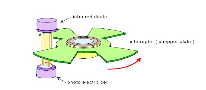
This sensor is made up of an infra red diode, a photo electric cell and a chopper plate. The chopper plate has for vanes regarding the number of cylinders. the upper picture shows a 4 cylinder engine. This has 3 wires ,a power, signal and a ground. When the cutter plate interferes with a light we get a high voltage and wen the cutter plate moves away from the light we get a low voltage.

this is the circuit diagram for the sensor. 5v goes into the infra red led and it emits light onto the photo electric diode which grounds the circuit. and there is 0v at signal. As the chopper plate interrupts the light the photo diode doesn't receive light so it does not let the 5v to ground. therefore we have a 5v at signal. This is how we get a square wave pattern shown below.


Our distributor needed a 12v suppy so we wired up a 12v supply and a ground. We connected the oscilloscope to the signal. As we turned it we got 11.55v when the chopper plate was interupting infra red light and 0.37v  when the plate moved away.


We got this pattern on the scope. It shows how its switching on and off.

A - when the diode is receiving the infra red light, circuit is grounded and voltage is 0.3v.
B - the infrared light is interrupted by the chopper plate and voltage increases to 11.55v.
C - chopper plate is still on between the infra red light therefore the voltage is still 11,55v.
D - chopper plate moves away from the light and now thee photo diode is receiving the light infra red light, the circuit is grounded therefore the voltage drops down to 0.3v.
E - the chopper plate is not interrupting the light so the circuit is still grounded.

The difference between the the 3 sensors are that the hall effect and optical have a digital pastern but the inductive type has an analogue pattern.The hall effect and optical have the same working principal but with different components.The difference in the optical and hall effect sensors is when the chopper plate cuts the light in the optical its firing time for the coil and when the chopper plate in the hall effect is interrupting  the magnetic field its dwell for the coil.


Hall Effect Sensors

Hall Effect Sensors


A hall effect sensor is a transducer (converts one type of energy to another) which varies in output voltage when magnetic field changes. This sensor has a digital signal.This sensor is generally inside distributors. Some manufactures use it for crank sensors with a special shielding around it to stop dirt ingress.

This consists of a chopper plate which has a fixed firing and dwell time, a magnet and a hall chip. We have 3 wires a power which is normally 5v, some manufactures use 12v. An earth and a signal.


A voltage is applied to the hall chip and a magnet is perpendicular to the face of the crystal conductor (hall chip). Then a small voltage is seen at the edge of the crystal conductor which is called the hall voltage. When the cutter plate cuts the magnetic field, the hall voltages ceases. when the cutter plate moves and theres a gap it lets the magnetic field go across the crystal conductor and we get the hall voltage back again.
There is a integrated circuit (circuit is on the second picture) which switches a transistor on and off to get the signal to ground. The hall voltage goes into a no inverting op amp to turn on the transistor which grounds the signal which is normally 5 v. When the chopper plate is interrupts the magnetic field the hall voltage ceases co there is no voltage at the base of the transistor therfore the sigal can not be grounded. This is how we get a 5v signal and when the chopper plate moves away we have hall voltage which lets the sigaal to ground giving us ov. this is how we get the square wave pattern.


I connected up the distributor to a power supply. Signal was connected to to the oscilloscope. Our distributor was not working properly as the voltages stayed to fluctuated from 2 - 3 volts. We did no get a square wave switching pattern.


I got this pattern from www.picoauto.com. This pattern shows how its switching. the dwell and firing time.When the cutter plate interrupts the magnetic field we have 2.4v and when it moves away we get hall voltage back again which grounds the 2.4v.


Speed/position Sensors / on car Crank Position Sensor and Cam Position Sensor

Speed or Position Sensors


These type of sensors tells the ecu the position of the component. This reacts to the change in speed of the component example the crankshaft sensor and the camshaft sensor.


I got an inductive type distributor and visually look in good condition. No damages or anything. Did a resistance check on the G pickup coil and showed 243 ohms on my multimeter. Manufactures specifications says it should be between 185-275 ohms so our reading shows that our g pickup coil is within specifications. The  NE pickup coil had a resistance of 486 ohms and specifications tells us that it should be between 370 - 550 ohms therefore out NE pickup coil is within specifications.

I then checked the air gap between the pickup coil and the reluctor tip with a brass feller gauge. I got 0.203mm which is within the specifications. So i didn't have to adjust it.


I Then connected an oscilloscope and spun the dizzy by hand and got an AC wave pattern.

A - reluctor tip is getting closer to the coil therefore air gap gets smaller and the magnetic field is increasing.
B - Air gap is smallest here and full magnetic saturation of the pickup has reached. The reluctor is lined up with the coil.
c - As the reluctor moves away magnetic field collapses across the coil and induces a voltage in the opposite direction. Back EMF.
D - reluctor tip moving away from the coil so voltages goes back to 0v.
E - Peak to Peak voltage (2.2v)


We connected the distributor on 2 channel and saw the wave form of both the NE and G signals when we turned the distributor. I have shown the peak to peak and time on the graph.


On car Crank Position Sensor (CKP)

The crank position Sensor is also know as the rpm sensor. I back probed the RPM signal wire and connected my multimeter on AC volts. Red probe on the signal and black probe to ground. Then i started the engine. I got a reading of 2.656V.  As i ireved the engine to about 2500 rpm the voltage increased to 6.95V.

Then i switched the the mulitmeter to read DC volts.  At idle speed the the voltage was 0.407V. Then i reved the engine to about 2500 rpm, the voltage increased to 1.341V.

I sthe switch the multimeter to read hertz. At idle i got 0.456k Hz. As i reved it up to about 2500 Rpm, it increased to 1.925k hz.

The Hz showed a more exact reading on how the rpm sensor working.

My engine had a magnetic pickup type crank sensor. The crank sensor is located inside the distributor and tells the ecu where TDC is. The crank sensor has one tooth to tell the position. This generates Ac voltage. As the speed increases the frequency and amplitude increases.

The air gap wrongly set on the pickup could upset the signal going to the ecu. There could be an open circuit somewhere in the wiring. If the ecu doesn't know the position on the crank shaft,the engine will crank but will not start.


On Car Cam Position Sensor

Our cam position sensor was inside the distributor.Thsi was also a magnetic pickup type.

I back probed the signal wire and connected the red probe of my multimeter to the signal and grounded the black probe. I got readings with different settings on the multimeter revin the engine.
DC volts - 57.5mV - 67.2mV 
AC volts - 0.95V - 3V
Hz - 17.9Hz - 6.7 Hz
duty cycle - 75% - 91.4%

Good measurements were the Hz reading and the Duty Cycle. It gradually increased and decreased as the engine RPM increased and decreased. With Duty Cycle we saw as the engine reved the the pickup coil was sending out voltages faster so the percentage it was working (sending out voltages) was more.


This is the same as the crank sensor but the reluctor wheel has more teeth on it.


Tuesday, September 28, 2010

Oxygen Sensor

Oxygen Sensor


The oxygen sensor is located in the exaust manifold before the catalytic converter. This is a ziconia type oxygen sensor with four wires. 2 wires for the heater circuit and a signal and a ground. The oxygen sensor needs to reach a tempeature of about 300 degrees celsius to work, therefore the heater is in the oxygen sensor for it to heat up quickly. This a very important sensor in the engine fuel control system. the sensor produces a voltage signal that recognises the amount of oxygen in the exhaust. More air will tell the engine is runnig lean and less air will tell the ecu that the engine is runnig rich. In closed loop the sensor goes rich and lean to control emissions. Heated oxygen sensor are good as it gets to closed loop quicker which improves fuel economy and reduces emmisions.


A- protector
B-
Ziconia sensor tip
C-Heater
D-sealing ring
E-Housing
F-Protective sleeve
G-21% outside oxygen to 2% exhaust oxygen runs lean
H-21% outside oxygen to 0% exhaust oxygen runs preferred
I-21% outside oxygen to 2% exhaust fuel runs rich

Voltage ranges from 0.2 volts (lean) to 0.8 volts (rich). A perfectly balanced fuel mixture gives an average reading of around 0.45 volts.


We carried out the experiment by connecting a multimeter to read voltage to the oxygen sensor. We then heated it up by a LPG gas torch and saw how it went rich when we had the torch close to it and and how it went lean when we took the torch away. when we had the flame on the sensor we got 0.9 v which told us that its detecting that its a rich condition. When we take the flame away the voltage drops to 0.2v this shows us thats its a lean condition.

I tried uploading the video here but did not work so i uploaded it on youtube. this is the link to it. http://www.youtube.com/watch?v=zejlhtYntsk. it clearly shows how we a get a voltage to a rich and lean (no flame to sensor) condition.


knock Sensor

Knock Sensor


The knock sensor is located in the block. In a 4 cylinder it will be between the second and the third cylinder. 6 cylinder engines may have 2 knock sensors. The knock sensor detects noise caused by pre ignition. The noise is know as knock or ping. The knock sensor helps the ecu to correct this by retarding timing etc.

The knock sensor puts out its own voltage. This is an AC voltage. There is a piezoelectric type material inside the knock sensor which induces a voltage when detects noise/vibration. The pizo crystals gets crushed due to the noise and releases electrons. The voltage decreases as the vibration decreases. The voltage is mV.


We connected an oscilloscope to the knock sensor to see the wave form and voltage it was putting out.We hit the knock sensor to cause vibration.


We saved this image from the oscilloscope. The image shows clearly when we hit the knock sensor and gradually the voltage is decreasing as to the noise vibration getting weaker. This is an Ac voltage.


Air Temp Sensor / On car

Air Temperature Sensor

The air temerature sensor (ATS) is also know as thermistor air (THa) and intake air temperature(IAT) sensor.This sensor is located in the ait cleaner box or sumwhere in the intake system. The air temp sensor helps the ecu calculate air density. Hot air is less dense than cold air. The ecu uses this information to do calculations for air fuel ratio mixes.

The IAT works exactly like the engine coolant temperature sensor. It is also a negative temperate coefficinet.When temperature increases resistances decreases and when temperature decreases resistace increases.


To do the experiment we did it like how we checked the ECT. As the IAT was made of plastic we didnt wana melt it by heating it up with a heater gun. And we also wouldnt have been able to know the temperature we heated it with. So we put it in water and heted it  over the stove. Temperatures were checked with a thermometer.At 20 degrees celsius the resistance was 2.9k. As we heated it up the resistance droped down to 800 ohms at around 50 degrees Celsius. This was within manufactures specifications and we could tell that the IAT was in good fine as the resistance gradually decreased when the temperature increased.  


Temperature (degrees celsius)
Resistance(ohms)
16
2.9k
20
2.5k
25
2.1k
30
1.7k
35
1.4k
40
1.1k
45
1k
50
800


On Car Intake Air Temperature

I found the IAT on the intake air clean box. I back probed the input wire  of the IAT and connected my multimeter to read DC voltage. Red probe to the input and the black probe to bappery negative post. Then i turned the igniton on.

I got a reading of 3.4v which is  more than the ECT voltage.

This shows that this is colder than the ECT sensor.


The IAT receives a 5v reference to the IAT thermistor. This is a NTC type thermistor which mean as temperature increases resistance will decrease. There is an internal resistor inside the ecu. When the air is hot, resistance decreases at the IAT so the voltage drop at the internal resistor is higher therefore less voltage goes to the IAT Input.The signal that the ecu looks at is voltage after the internal resistor as shown in the above wiring diagram. So when theres hot air signal sees a low voltage. When the air gets cold, resistance is high at the IAT and more voltage is needed to go through the thermistor so the signal sees a high voltage.

The IAT works with the MAP sensor to calculate the amount of air entering the engine. Cold air is more dense the hot air. So when the IAT senses cold air the ecu will need to open the injector longer to get the air fuel mixture right. If there is hot air entering the engine and the signal at the IAT is telling the ecu that theres cold air,the injectors will squirt more fuel making the air fuel mixture rich which will make the engine suffer from poor fuel economy and bad emmisions. If theres cold air getting in but the IAT is telling the ecu that theres hot air the mixture will be lean therefore the car will loose power.


Things that can cause an incorrect IAT signal to the ECU:
 - poor grounding at the ECU (connection corroded)
 - poor ECU grounding
 - Theres not a good supply voltage from the ECU
 - Open Circuit on the earth side or power side in the circuit
 - Bad thermistor


Thermo Fan Switch

Thermo Fan Switch

The Termo fan switch is mounted on the radiator core.The thermo fan switch is very important as it the switch to turn the radiator fan on and off. The switch is closed when it is cold and when it reaches a certain temperature there is an open circuit to turn on the fan.


We connected a multimeter to check resistance and put it in a bowl of water with the stove heating the water.We got a reading of 0.3 ohms which showed us that the switch was closed. When the temperature increased to about 93 degrees the meter read OL, which showed us that the switch was now open.So the fan would go on at around  93 degrees  Celsius to cool the radiator. This is not a thermistor. The thermo fan switch is working fine and is according to the manufacturer's specifications.


Engine coolant Temperature Sensor / On car

Engine Coolant Temperature Sensor


This sensor is also know as CTS (coolant temperature sensor) and THw (thermistor water). This sensor measures the change in coolant temperature. This sensor is generally located on the thermostat housing. This is a NTC (negative temperature co-efficient). this means when the temperature is high resistance is low and when the temperature is low resistance is high. This sensor is very important for cold starts to warm up the engine. The ecu enriches the fuel mixture and etc.


To do our experiment we connected our ECT to a multimeter to read resistance. We dipped it to a bowl of water which was on the stove to heat it up. Also used a thermometer to check the temperature of the water. The resistance decreased as the water heated up.At 20 degrees Celsius we had a resistance of 2.2k ohms and it decreased down to 300 ohms at 80 degrees Celsius. The readings i got is within manufactures specifications.


Water Temperature (degrees Celsius)
Resistance(ohms)
20
2.2k
30
1.8k
40
1.2k
50
800
60
600
70
400
80
300


The ecu has and internal resistor which reads the voltage after the resistor as show on the wiring diagram on the ECT, when the engine is cold there is a high resistance at the thermistor therefore there is a higher voltage drop at the thermistor so more voltage will be needed at the thermistor. Voltage drop at the internal resistor at the ecu is low and a higher voltage at signal is achieved. when the engine warms up there is a low resistance therefore a low voltage drop at the thermistor and a higher voltage drop at the internal resistor in the ecu, so a less voltage goes to the thermistor. The signal voltage is low because more voltage gets used up at the internal ecu resistor.


On Car Engine Coolant Temperature Sensor)

We located the Ect sensor and back probed the supply wire. Connected the multimeter (on DC volts) red probe to the supply and black probe to ground. We turned the igniton on.

With a cold engine we got a reading og 1.835V. When we started the  started the engine, the voltage decreased to 0.802V when the engine was at normal operating temperature. SO i conclude as the engine arms up the voltage at signal decreases.

I have described how the ECt works on top of the page in the off car part with the wiring diagram.

The Ecu gets information from the ect to see if the engine is cold or warm. If the engine is cold the ecu will make the car rich to heat it up quicker. This is done by opening the injectors longer. When the car warms up the engine will look at the ECT and re adjust injection timing.

Things that could affect the Signal voltage at the ecu :
 - Incorrect Reference voltage getting to the Thermistor due to a high resistance on the supply side.
 - Resistance at ground or the ecu having a bad ground. If theres a high resistance on the ground , the signal will have a high voltage which will tell the ecu that the engine is cold all the time.
 - the thermistor not working


Ground Coolant Temperature Sensor

I back probed the ground wire on the ect and connect my multimeter(on DC volts) red probe to the ECT ground and black probe to the battery post. I started the engine.

I got a reading of 0.3mV telling me that the grounding was good. It is very important to check the ground to dignose problems with the ECT. If the ect has a resistance at ground, the signal voltage will be high telling the ecu that the engine is cold. The ecu will then open the injectors longer making the car rich. The engine will suffer from poor fuel economy and bad emmisions.

Things that can cause this are are:
 - loose  grounding connections caused from vibrations and thermal stress.
 - Electrical terminals corroded by coolant
 - Loose ecu ground.
 - Battery terminal corroded not making a good connection with the negative battery post.

The wiring diagram is on the upper part of the page.