Ballast Resistors
The ballast resistor is in series with the primary circuit. It is between the ignition switch and the postive terminal of the igniton coil.During cranking a parallel circuit form the starter circuit bypasses the ballast resistor. There will now be battery voltage at the coil which will speed up the current flowing to the primary circuit. The magnetic field will be stronger therefore more voltage will be at the secondary which will make a stronger spark.
When the engine is running, the ballast resistor provdies a voltage drop in the primary circuit which lowers the voltage to what coil is designed to operate with.
Ballast resistor - BR3
Manufactures Specifications - 1.5 - 1.7 ohms
We got 1.7 ohms when we did a resistance check on our ballast resistor and this is within manufactures specifications.
Ballast Resistor - BR3
Manufactures Specifications - 1.5 - 1.7 ohms
We got 1.9 ohms when we checked the resistance and this is not serviceable as its not within the manufactures specification.
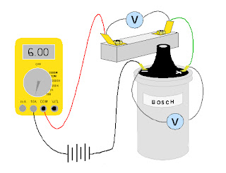
To measure the current draw and voltage drop i wired up the ballast resistor in series with the coil primary to a 12v power supply. I also connected an ammeter in series to see the current draw.
Current Draw - 5.6 Amps
Coil measured voltage drop - 1.8V
Ballast Measured voltage drop - 9.7V
Calculations
Ballast resistor - 1.7 ohms
Coil primary resistance - 0.3 ohms
Power supply - 12V
resistance in series circuit is added together therefore the resistance in the circuit is 2 ohms.
using the formula V = I x R
12V/2ohms we get the current of 6amps.
voltage drop at ballast resistor - 6amps x 1.7ohms = 10.2V
Voltage drop at coil - 6amps x 0.3ohms = 1.8V
Voltage drop at coil - 6amps x 0.3ohms = 1.8V
Our measured findings are very close to out calculated findings. There was probably a little voltage drop at wire connections or the power supply was not exactly 12V.


No comments:
Post a Comment