Wednesday, October 6, 2010

Scan tool Diagnostics (WS5)

Scan Tool Diagnostics


We did testing on a 2004 Honda Accord.


Type of information 
Letters to decribe 
Value of data
Unit for data

Engine RPM
RPM
793
RPM
Engine Coolant temperature
ECT
91
C
Intake air temperature
IAT
65
C
Fuel Injection opining pulse
FI
2.41
ms
Vehicle Speed
VS
0
Km
Oxygen Sensors(S)
O2 (S)
0.6
V
Fuel Tim
Short
long
1.02
0.99
%
Power Steering

0.05
V
Idle control
Ic
On

Air conditioning condition
A/C
On/off
C
Exhaust Gas Recirculation
EGR
0
lef
Fuel Evap or purge condition

no
%
Malfunction Indicatr light
MIL
YES

Bometric Pressure
Bp
8.5
Hz


There was no codes.

The lectures put in a code. The code showed up in the scan tool as throttle  position sensor no values.

We visually inspected the engine bay and found the TPS sensor connector unplugged. We then replugged the connector nad cleared the codes by the clear codes feature in the scan tool. We re checked for codes and no codes were shown.

Live data is very important at fault finding as sometimes there are no codes shown up on the scan tool but there still might be a problem. Or sometimes there may be a list of codes showing up on the scan tool that may lead to a different finding when looked at live data. example a grounding problem which all sensor codes showing up because of using the same grounding wire. With live data you can analyze and come up to conclusions for repairs. Live data should be compared to manufactures specifications or parameters. Live data should be within specs

Scan tools just makes life easier and give indications to where the problem is and then you can use live data to come to accuate conclusions of the problem. Other expensive scan tools have built in oscilloscopes where you can see patterns which are very useful in fault finding. 

Flash Codes (WS2)

Flash Codes

I did my flash codes testing on a Toyota 4A-FE engine. I checked if my check engine light was working. My tutor had created some faults in the engine. 

I located the diagnostics plug. With the ignition off i had bridged terminal TE1 and E1. This creates a short circuit and gets the codes out by blinking the check engine light.

The lights started blinking and giving me codes. Every blink indicated a number eg. 2 blinks then a pause and 4 blinks was 24. then a long pause and then another code. The codes i got was 24, 41 and 31.

From the service manual i found out what each code meant.
24 - intake air temperature circuit
41 - throttle position sensor circuit
21 - vacuum sensor circuit

I did a visual inspection to all the circuit and found that all the lugs were not clicked in properly. The connectors were not in properly with the sensors.

I then plugged back the connectors and cleared the codes by taking out the ecu fuse for about a minute. Then i rechecked the system for codes by doing the same procedure for testing. The light kept blinking. It was code 1 saying everything is normal.

This faults wouldn't have let the engine to start and if it started it would hesitate and will be rough. 

After finding the fault codes you should be doing a volt drop test to check at grounds and power supply. checking voltage outputs at signal.


Fuel Pressure and Flow (WS4)

Fuel Pressure and Flow


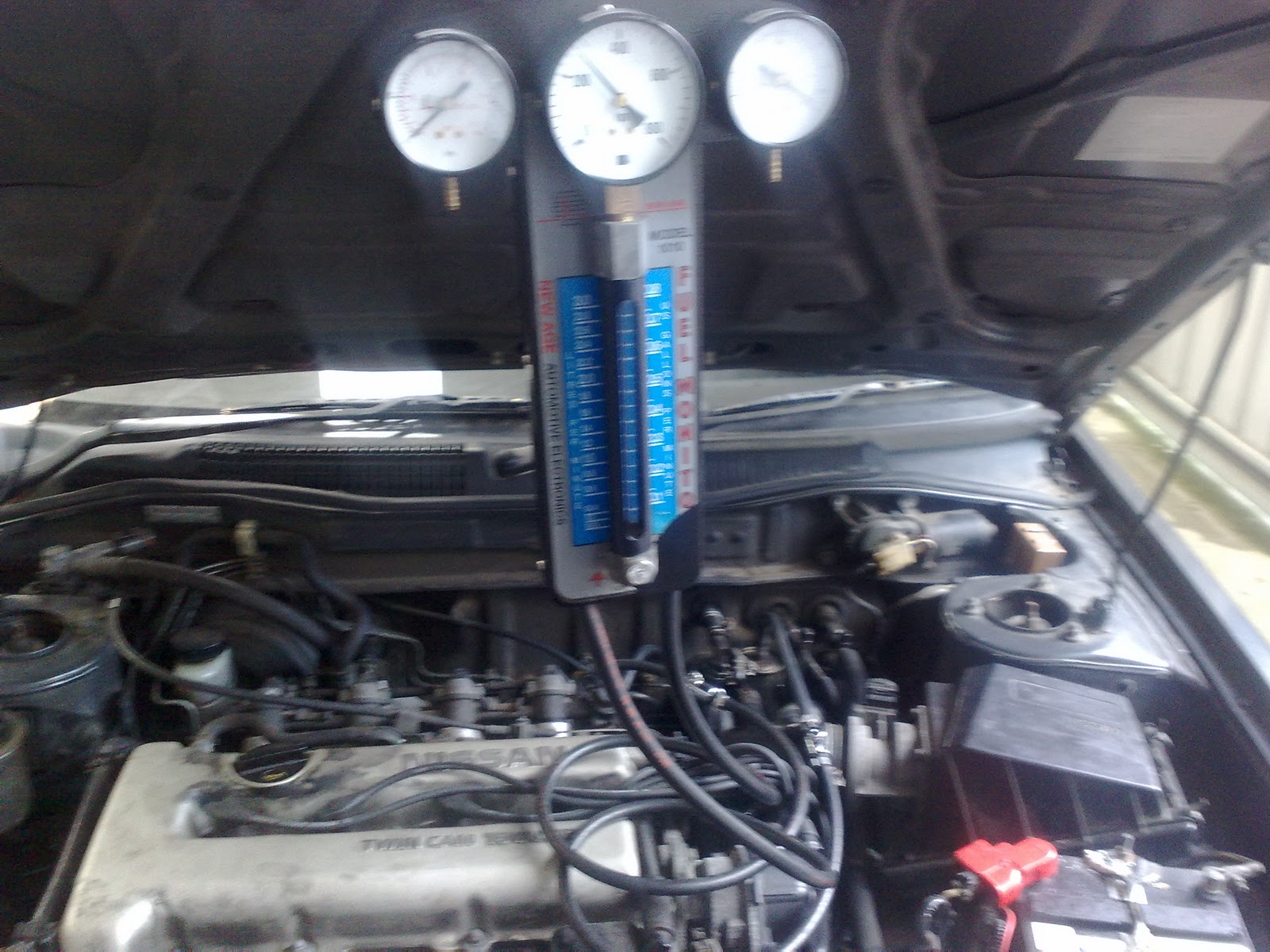
Before doing any test we located the closed fire extinguishers which was in workshop room 100. We did testings on a Nissan Primera.


Before be connected the pressure gauge to the fuel system we had to take the fuel pressure out. We took the fuel pump fuse out and ran the engine till it died out. Now it was safe to disconnect fuel lines and connect in the pressure gauge. Then i put the fuse back on and turned the ignition key on. I visually inspected all connections and there was no leaks. We measured  270Kpa.


We then started th engine and at idle the pressure was 275Kpa.


To check for maximum pressure we clamped the return line with a clamping tool and the pressure rises to 480Kpa.


To check at wide open throttle we disconnected the vacuum line going to the fuel pressure regulator which gave us a reading of 320Kpa.


To check for residual pressure we turned off the engine and watched the pressure for 5 minutes. Pressure was 250Kpa and stayed the same telling us there was no leaks in the system.


We got the fuel volume reading of 2.2 litres every minute. Specifications say half a litre every 15seconds. 2.2L divided by 4 is .55. Therefore it is 0.55 litres every 15 seconds.


After doing all testings  we removed fuel pressure form the system again and removed the fuel pressure gauge.Connected back all fuel lines and vacuum line to fuel regulator. And started the engine back up and check for any leaks. Everything was OK.


It is important to check for a vehicles fuel pressure and flow to know if the engine is operating properly and to diagnose problems eg; weak fuel pumps, blocked fuel lines and etc. Fuel pressure should be within specifications for optimum performance of the engine.


With low fuel pressure the engine will be hard to s start and if it starts it might die after a few seconds. This  can be caused  by a weak fuel pump. At high revs the car wont have power when you will need more pressure for the injectors to spray more fuel, there fore the car will run lean. The engine will be surging. Low fuel flow can be caused by a block fuel filter and the performance will be really sluggish. The engine will loose power as there is not enough fuel supplied to the system.


A high fuel pressure will cause the engine to run rich. The injectors will be spraying more fuel therefore the fuel economy will rise up. The idle will be rough and will have black smoke out the exhaust


Faulty pressure regulator may make the fuel pressure in the fuel rail to be high or low. The engine will be running rich due to high pressure and lean due to low pressure. The above symptoms will occur. The regulator will not maintain a steady pressure between the fuel line to the injectors and the air in the intake.

Tuesday, October 5, 2010

Wiring up Ignition Systems

Distributor Ignition


In this setup i wired up a 12v supply to the coil and it was grounded by the module. The secondary of the coil was connected to the spark plugs. the trigger was connected to the distributor. As we spun the distributor the primary circuit was grounded and ungrounded. The magnetic field collapsed across the secondary winding when the circuit was ungrounded. Spark happened at the spark plug as the circuit was ungrounded. We had to spin the distributor pretty fast to see the spark because this was a magnetic distributor and we need to turn it fast enough for it to trigger.

Coil Over Ignition


This is the coil over ignition setup. This type has a coil for each spark plug. The coil secondary is directly connected to the spark plug. We used a 5v function generator to trigger the module for the circuit to ground and unground.As we played with the function generator and speed it up, the spark came on faster.

Single Coil and function Generator


This setup is a single coil and function generator triggering the module. The module had 4 pins. A 12v supply, trigger, coil ground and battery ground. We wired it up according to my wiring diagram above. The function generator triggered the module to ground and unground. As there was 5v at the module it would let the coil ground. when the 5v was turned off,the primary winding could not ground therefore the magnetic field collapsed across the secondary winding creating a spark at the spark plugs.


Building an Ignition Module

Firstly to find the  base resistor at the base to switch on collector emitter we have to find out about our transistor.
Maximum current at base is ! amp.
The function generator will give 5v.
we will also minus the voltage drop across the base and emitter.
5v - 0.7v - 4.3v.
R = V / I therefore 4.3v / 1amp = 4.3 ohms.

Then we would calculate the resistor R3.
power supply 12v - voltage drop at vce of 0.5v = 11.5v
resistance in ignition coil 3.8 ohms.
12v / 3.8 ohms =  3.16amps
11.5v / 3.16amps = 3.63 ohms.
I used a 4 ohm resistor.

When the function generator gives 5v to the base the primary winding is then grounded through the collector an emitter. When the 5v signal at base is taken away, the magnetic field collapses across the winding into the secondary winding and creats a spark at the spark plug.


Monday, October 4, 2010

Ballast Resistors

Ballast Resistors
The ballast resistor is in series with the primary circuit. It is between the ignition switch and the postive terminal of the igniton coil.During cranking a parallel circuit form the starter circuit bypasses the ballast resistor. There will now be battery voltage at the coil which will speed up the current flowing to the primary circuit. The magnetic field will be stronger therefore more voltage will be at the secondary which will make a stronger spark.

When the engine is running, the ballast resistor provdies a voltage drop in the primary circuit which lowers the voltage to what coil is designed to operate with.

Ballast resistor - BR3
Manufactures Specifications - 1.5 - 1.7 ohms
We got 1.7 ohms when we did a resistance check on our ballast resistor and this is within manufactures specifications.

Ballast Resistor - BR3
Manufactures Specifications - 1.5 - 1.7 ohms
We got 1.9 ohms when we checked the resistance and this is not serviceable as its not within the manufactures specification.

To measure the current draw and voltage drop i wired up the ballast resistor in series with the coil primary to a 12v power supply. I also connected an ammeter in series to see the current draw.

Current Draw - 5.6 Amps
Coil measured voltage drop - 1.8V
Ballast Measured voltage drop - 9.7V

Calculations

Ballast resistor  - 1.7 ohms
Coil primary resistance - 0.3 ohms
Power supply - 12V

resistance in series circuit is added together therefore the resistance in the circuit is 2 ohms.

using the formula V = I x R
12V/2ohms we get the current of 6amps.
voltage drop at ballast resistor - 6amps x 1.7ohms = 10.2V
Voltage drop at coil - 6amps x 0.3ohms = 1.8V

Our measured findings are very close to out calculated findings. There was probably a little voltage drop at wire connections or the power supply was not exactly 12V.


Ignition Coils

Ignition Coils
Inside an ignition coil there are 2 sets of windings. The primary winding and the secondary winding. The primary winding gets battery voltage and is grounded by the distributor when its a dwell period. When the circuit is broken into the firing period, the magnetic field collapse (back EMf) across the secondary winding. Because the winding in secondary are a ration of 1:100 the voltage at the secondary is way higher, which is then used to jump the spark at the plugs.

I did a resistance check of the primary winding by connecting a multimeter in resistance check and connected it to the outside terminals. The secondary was done according to the picture above.

Coil NO: IC013
Coil 1 primary: 0.3 ohms
Coil 1 secondary: 6.82K ohms
The leakage test have OL so it tells us that it is OK.
Coil didn't have any numbers on it.
Coil 2 primary: 4.3 ohms
Coil 2 secondary:6,43K ohms
The leakage test have OL so it tells us that it is OK.

Could not find manufactures specifications but test look OK. Coil 1 would need a ballast resistor to work in the primary circuit as the resistance is very low.


Wasted Spark Coil pack

In this type one coil will serve 2 spark plugs. It will generate 2 parks per cycle to both the cylinders.The wasted spark system is more reliable than a single coil with a distributor and cheaper than coil-on-plug.

I could not get a resistance reading for the coil primary as this is an enclosed unit and is inside.

Coil ! Secondary - 8.3 ohms
Coil 2 Secondary - 8.5 ohms

I could not find manufactures specifications. Visually and from my testings it looks good.


Fuel Injectors / on car


Fuel Injector


A fuel injector is a way for mixing fuel into air in an engine. It opens and closes by signal from the ecu. The longer its open more fuel will be injected. This is an actuator. The ecu receives information form the sensors and thens controls the time the injectors are open.


We did a resistance check in the windings to check if the injector is working properly. All our resistances were within manufactures specifications. Our resistances were between 14 - 17 ohms which told us our injectors were without resistors. We also did an earth leakage test to form the earth terminal of the injector to the body of the injector to see if any part of the winding is shorting to earth. We got an OL reading which told us that nothing is getting grounded through the body. The injectors were working properly.


Then we did an audible check to hear the injector opening and closing. I heard a sharp click as the injector opened and closed. This shows us that its in good working condition.

Other engine problems that could give the results as an injector not opening are :
 - no fuel in the tank
 - fuel pump not working
 - Corrosion at the injector connector.
 - Fuel filter blocked

We then connected our injectors to a injector tester to check for spray pattern , leakage and flow test.


We need to check if the injector is injecting the fuel in an even cone shape so that the fuel gets atomized. There should be no dripping.


All spray patterns and leakage tests were fine. I think the injectors were cleaned  in the ultrasonic cleaner before i tested it.


On Car - Battery Voltage To Injectors


The voltage measured was 14.01V. We check the voltage supply at the injectors to check of any problems in the circuit before the injector. If we do not have supply voltage the injector wont open properly or wont work at all. 

If we find a lower voltage at the injectors than the battery this means there is a resistance somewhere between the injector and the battery. There might be corrosion in the connectors or poor connections.This will lead to the injectors not opening properly or just being dead( not firing at all).


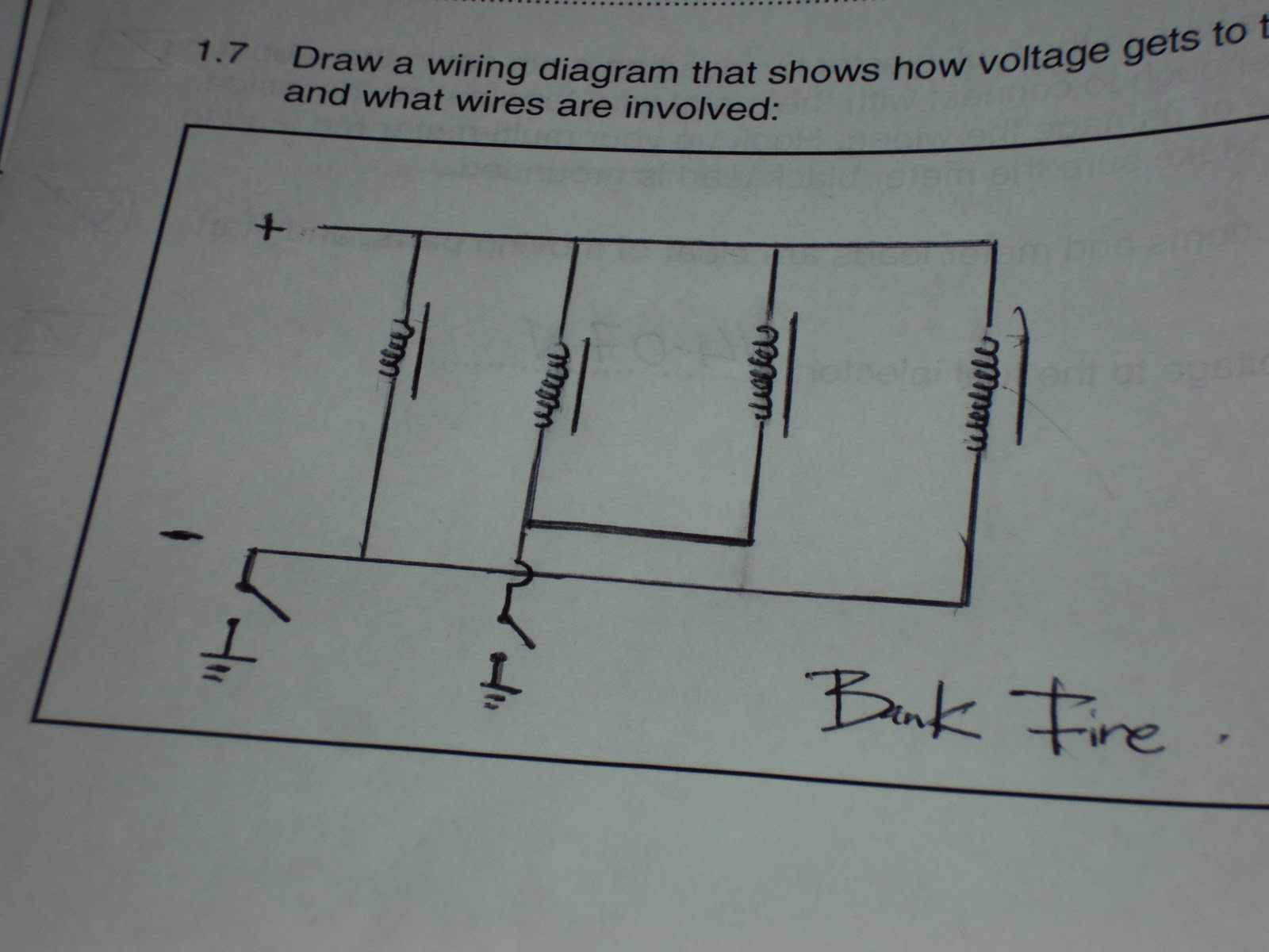
The injectors on my engine had a bank fire configuration.